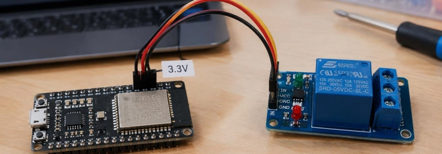
An ESP32 GPIO outputs a 3.3 V signal, while many common relay modules are designed around a 5 V power supply. This difference can leave the relay partially activated, prevent it from switching off reliably, or cause intermittent clicks. You cannot resolve this by looking only at the coil voltage: you also need to check how the module interprets the input signal.
The guide published on DEV Community, originally on iot.gripe, recommends checking coil voltage, logic compatibility, trigger polarity, isolation, and contact capacity before buying. Random Nerd Tutorials shows that some modules do accept the ESP32's signal level: the one it describes triggers below about 2 V. The difference between these cases explains why one board can control a module without problems but fail with another that looks equivalent at first glance.
The coil and the input have two different requirements
A mechanical relay uses a small current to actuate an electromagnet, which moves contacts that can open or close another circuit. The GPIO must not power the coil directly: the module includes a transistor to supply that current and a diode to protect the circuit when the coil is deactivated. It may also include an optocoupler, an indicator LED, and COM, NO, and NC terminals.
It is worth separating two questions that are often conflated in product specifications. The first is what voltage the coil needs to operate: the iot.gripe guide notes that 5 V is most common, although there are modules with 3.3 V coils. The second is what level the IN input must receive to activate or deactivate the control circuit. The fact that the coil is 5 V does not, by itself, mean that a 3.3 V GPIO is incompatible; and an advertisement saying “ESP32 compatible” does not necessarily clarify how that input is designed.
The experience described by Random Nerd Tutorials is a concrete example: its module's input activates when it drops below approximately 2 V, so it can respond to an ESP32 signal. By contrast, the iot.gripe guide warns about 5 V modules with an optocoupler and active-low triggering where a 3.3 V HIGH may not be enough to turn the optocoupler off completely. The relay may remain stuck, click intermittently, or leave its LED dimly lit.
What to check before choosing a module
The first check is that the manufacturer specifies that the input is compatible with 3.3 V logic. If the specifications are unclear, do not infer compatibility from the supply voltage alone: test the module with the ESP32 before connecting it to a load. Another option is to choose a module with a 3.3 V coil, although that does not replace checking its control input.
Next, identify whether triggering is active-low or active-high. In the first case, IN activates the relay when it goes LOW; in the second, it activates it when it receives HIGH. Many inexpensive modules are active-low, and some let you select the logic with a jumper. Polarity affects both the logic wiring and the program: if it is reversed, the command the developer thinks of as “on” may turn the relay off, and vice versa.
A JD-VCC jumper may allow you to separate the coil power supply from the control section. The iot.gripe guide suggests removing the jumper and powering the optocoupler section with 3.3 V and the coil separately with 5 V. Random Nerd Tutorials explains that removing the jumper from its module requires a separate power supply for the electromagnet and that the optocoupler can physically isolate the two circuits. This arrangement depends on the specific module design: follow its schematic and do not assume that the presence of the jumper guarantees isolation in every configuration.
You also need to choose the contact type according to the desired behavior. COM is the common terminal; NO (normally open) keeps the circuit open until the relay is activated, while NC (normally closed) keeps it connected until activation. For a lamp that should turn on only when it receives a command, Random Nerd Tutorials uses NO. This is a decision about the electrical state of the load, distinct from the HIGH or LOW logic that activates the module input.
Finally, check the number of channels and the contact capacity. A multichannel module controls several outputs, but each channel adds an input and a load that needs power. The iot.gripe guide cites a 10 A at 250 V AC rating as a common specification and recommends leaving a margin relative to the load; it does not present this rating as suitable for every appliance. For large loads, such as stoves, heaters, or motors, it advises staying well below the limit and using appropriate contactors and an electrician.
Power, isolation, and safety
On a board powered by USB, the 5 V pin can usually power one or two relays, according to the iot.gripe guide. For several relays, it recommends a separate power supply with a common ground. Random Nerd Tutorials also distinguishes the JD-VCC control supply, which powers the electromagnet. The choice between a single supply and a separate one affects the setup and isolation; do not make it solely for convenience if the module will be connected to mains electricity.
An optocoupler adds separation between the microcontroller signal and the relay circuit, but the power supply arrangement matters: Random Nerd Tutorials states that, with the jumper installed, VCC and JD-VCC are connected and the electromagnet is powered directly from the board's power pin; in this configuration, the circuits are not physically isolated from each other. Removing the jumper and using a separate power supply for the coil enables the isolation provided by the optocoupler, according to its explanation.
The initial test should be performed with the module disconnected from mains. iot.gripe recommends checking that it switches on and off using the LED and the relay click before connecting a load. BlueGrays also suggests using an LED first instead of a lamp. Mains electricity poses a risk of electric shock or fire: if you do not have experience with electrical installations, the iot.gripe guide advises leaving that connection to an electrician. Random Nerd Tutorials says to keep everything disconnected from mains while programming or wiring, and to place the final assembly in an enclosure that prevents AC terminals from being exposed.
Startup is also part of the design
Even if the logic works during normal operation, the relay may briefly activate at startup. The cause identified by iot.gripe is that the pin may be in an undefined state until the program configures it. It therefore recommends setting the off state as early as possible in setup() and avoiding boot pins; for the ESP32-C3, it cites GPIO 2, 8, and 9 as pins to avoid because their state during startup may activate the relay momentarily.
The code should explicitly represent the module's polarity instead of scattering inversions across different parts of the program. The iot.gripe guide shows a function that converts the desired logical state to HIGH or LOW depending on an active-low option. BlueGrays uses the same principle in its example for GPIO 26 and sets the off state when configuring the output. It is a small design choice with a practical effect: it makes the relationship between the application command and the electrical level sent to the pin clear.
The assigned pin also deserves checking. Random Nerd Tutorials connects its example to GPIO 26 and notes that another suitable GPIO can be used; BlueGrays likewise suggests GPIO26 as the default. These are not reasons to copy that number without checking the board: the iot.gripe guide says to avoid boot pins on the ESP32-C3, and the wiring must match the specific model being used.
When another technology is a better choice
For turning a light on and off a few times a day, the iot.gripe guide considers a mechanical relay the simplest and most reliable option. It has physical contacts and clicks; its service life is limited by those contacts. A solid-state relay (SSR) has no moving parts and operates silently, but it may allow a small current to pass when switched off. With some LED bulbs, this leakage is enough to cause a faint glow or flickering.
According to that guide's table, neither an SSR nor a mechanical relay is generally suitable for dimming. To dim a load, it proposes a TRIAC with the appropriate circuit; it also warns that leakage current may flow when it is off. The choice therefore depends on the specific task: frequent, silent switching points to an SSR; a light switched on occasionally, to a mechanical relay; dimming, to a TRIAC with its appropriate circuit.
The final criterion is not to buy the module with the most channels or the one advertising a 5 V coil. It is to confirm that the input recognizes the ESP32's 3.3 V, decide what power supply and isolation the setup requires, establish a safe state during startup, and check switching without a mains load. If the manufacturer does not specify logic compatibility, that check must happen before connecting the lamp.
Sources: DEV Community, Random Nerd Tutorials, BlueGrays